Steel wire rope rejection criteria
Discard the wire rope in accordance with current regulations or according to the manufacturers recommendations.
Only a qualified and experienced person should be responsible for discard.
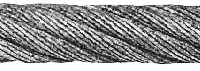
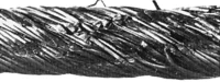
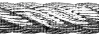
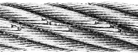
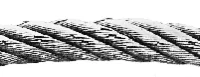
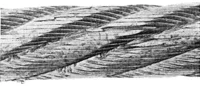
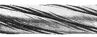
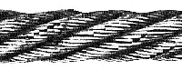
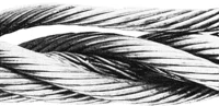
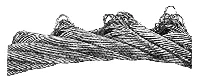
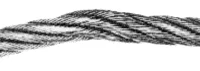
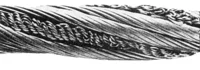
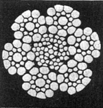
The pictures show typical examples of wire rope deterioration.
WARNING! Failure to take adequate precautions could result in injury.
| Rope category number |
Number of load-bearing wires in the outer layer of strands in the rope a
|
Number of visible brokenb outer wires over a length of: | |||||
|---|---|---|---|---|---|---|---|
| Section of rope working in steel sheaves and/or spooling on a single-layer drum | Sections of rope spooling on a multi-layer drum c | ||||||
| Classed M1 to M4 or class unknown d | All classes | ||||||
| Ordinary lay | Lang lay | Ordinary and Lang lay | |||||
| RCN | n | 6de | 30de | 6de | 30de | 6de | 30de |
| 1 | n ≤ 50 | 2 | 4 | 1 | 2 | 4 | 8 |
| 2 | 51 ≤ n ≤ 75 | 3 | 6 | 2 | 3 | 6 | 12 |
| 3 | 76 ≤ n ≤ 100 | 4 | 8 | 2 | 4 | 8 | 16 |
| 4 | 101 ≤ n ≤ 120 | 5 | 10 | 2 | 5 | 10 | 20 |
| 5 | 121 ≤ n ≤ 140 | 6 | 11 | 3 | 6 | 12 | 22 |
| 6 | 141 ≤ n ≤ 160 | 6 | 13 | 3 | 6 | 12 | 26 |
| 7 | 161 ≤ n ≤ 180 | 7 | 14 | 4 | 7 | 14 | 28 |
| 8 | 181 ≤ n ≤ 200 | 8 | 16 | 4 | 8 | 16 | 32 |
| 9 | 201 ≤ n ≤ 220 | 9 | 18 | 4 | 9 | 18 | 36 |
| 10 | 221 ≤ n ≤ 240 | 10 | 19 | 5 | 10 | 20 | 38 |
| 11 | 241 ≤ n ≤ 260 | 10 | 21 | 5 | 10 | 20 | 42 |
| 12 | 261 ≤ n ≤ 280 | 11 | 22 | 6 | 11 | 22 | 44 |
| 13 | 281 ≤ n ≤ 300 | 12 | 24 | 6 | 12 | 24 | 48 |
| Ropes having outer strands of Seal construction where the number of wires in each strand is 19 or less (e.g. 6 x 19 Seal) are placed in this table two rows above that row in which the construction would normally be placed based on the number of load bearing wires in the outer layer of strands. | |||||||
| a) Filler wires are not regarded as load-bearing wire and are not included in the values of n. b) A broken wire has two ends (counted as one wire) c) The values apply to deterioration that occurs at the cross-over zones and interference between wraps due to fleet angle effect. d) Twice the number of broken wires listed may be applied to ropes on mechanisms whose classification is known to be M5 to M8. e) d= nominal diameter of rope. |
|||||||
 |
1. Mechanical damage due to rope movement over sharp edge projection whilist under load. |
|---|---|
 |
2. Localised wear due to abrasion on supporting structure. Vibration of rope between drum and jib head sheave. |
 |
3. Narrow path of wear resulting in fatigue fractures, caused by working in a grossly oversize groove, or over small support rollers. |
 |
4. Two parallel paths of broken wires indicative of bending through an undersize groove in the sheave. |
 |
5. Severe wear, associated with high tread pressure. Protrusion of fibre main core. |
 |
|
|
|
7. Corrosion of severe degree caused by immersion of rope in chemically treated water. |
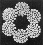 |
8. Internal corrosion prominent while external surface shows little evidence of deterioration. Complete lack of strand gap suggests internal degradation. |
 |
9. Typical wire fractures as a result of bend fatigue. |
 |
10. Wire fractures at the strand, or core interface, as distict from "crown" fractures, caused by failure of core support. |
 |
11. Break up of the steel core resulting from higt stress application. Note nicking of wires in outer strands. |
 |
12. Strand core protrusion as a result of torsional unbalance created by "drop ball" application (i.e. shock loading). |
 |
13. Typical exampel of localised wear and deformation created at a previously kinked portion of rope. |
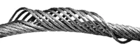 |
14. Multi strand rope "bird caged" due to torsional unbalance. Typical of build up seen at anchorage end of multifall crane application. |
 |
15. Portrusion of steel core resulting from shock loading. |
 |
16. Substantial wear and severe internal corrosion. High tension abrasion and corrosive environment are combined in this example. |