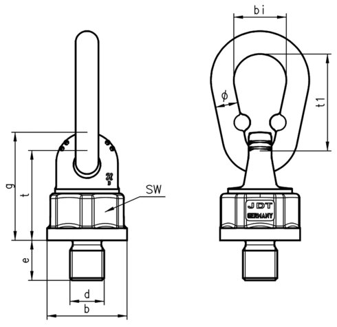
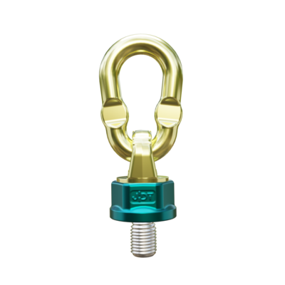
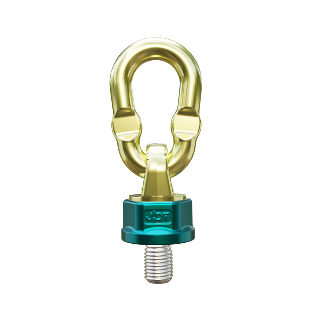
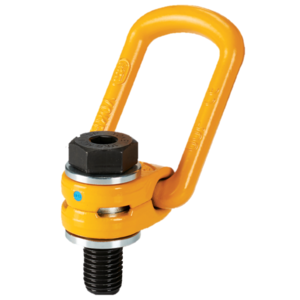
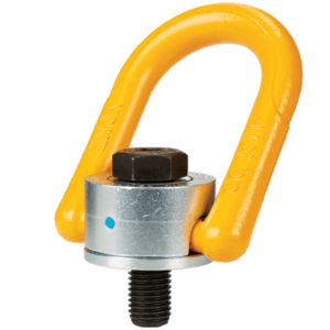
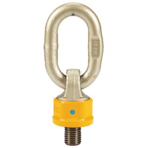
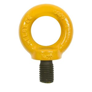
The eyes can be loaded with working load limit in all directions. All the eyes are pivoted to avoid breakage in the eyes, which also make it possible to fold it aside when it is not in use. Furthermore it has a ball beared swivel which makes the lifting eye to always stand in the correct direction to the load.
- Material: Eye and swivel of alloy steel grade 10.
- Marking: CE-marked, WLL.
- Finish: Painted.
- Note: The surface that the lifting eyes shall be attatched to shall be flat and tolerate the load it is going to be exposed to.
- Safety factor: 4:1.
- Grade: 10


Select a row from the table below, then click the add to cart button
Download CAD

Download CAD by choosing the desired product from the table above and the format from the menu below. Click "Get CAD" and after the load reaches 100% you can click on the download icon to download it. Please note that CAD drawings are only available if the icon at the right side of the table above is colored and not grayed out.
Get CAD
Download
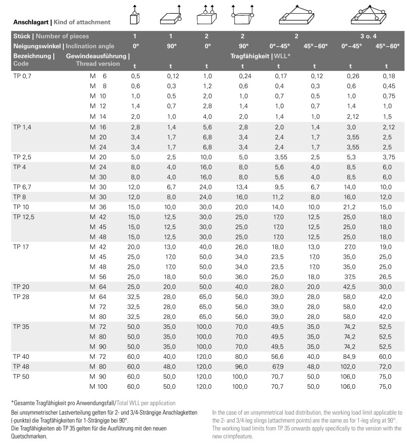
Load diagram
Kind of attachment
|
|
|
|
|
|
|
|
|
|
|||||||||
Number of legs
|
|
1
|
1
|
2
|
2
|
2
|
|
3+4
|
3+4
|
|||||||||
Angle of inclination
|
|
0°
|
90°
|
0°
|
90°
|
0°-45°
|
45°-60°
|
0°-45°
|
45°-60°
|
|||||||||
Code
|
Thread
|
Load capacity
|
|
|
|
|
|
|
|
|||||||||
|
|
tons
|
|
|
|
|
|
|
|
|||||||||
TP 0,7
|
M 10
|
1,0
|
0,5
|
2,0
|
1,0
|
0,7
|
0,5
|
1,0
|
0,75
|
|||||||||
|
M 12
|
1,4
|
0,7
|
2,8
|
1,4
|
1,0
|
0,7
|
1,4
|
1,0
|
|||||||||
|
M 14
|
2,0
|
1,0
|
4,0
|
2,0
|
1,4
|
1,0
|
2,12
|
1,5
|
|||||||||
TP 1,4
|
M 16
|
2,8
|
1,4
|
5,6
|
2,8
|
2,0
|
1,4
|
3,0
|
2,12
|
|||||||||
|
M 20
|
3,4
|
1,7
|
6,8
|
3,4
|
2,4
|
1,7
|
3,55
|
2,5
|
|||||||||
|
M 24
|
3,4
|
1,7
|
6,8
|
3,4
|
2,4
|
1,7
|
3,55
|
2,5
|
|||||||||
TP 2,5
|
M 20
|
5,0
|
2,5
|
10,0
|
5,0
|
3,55
|
2,5
|
5,3
|
3,75
|
|||||||||
TP 4
|
M 24
|
8,0
|
4,0
|
16,0
|
8,0
|
5,6
|
4,0
|
8,5
|
6,0
|
|||||||||
|
M 30
|
8,0
|
4,0
|
16,0
|
8,0
|
5,6
|
4,0
|
8,5
|
6,0
|
|||||||||
TP 6,7
|
M 30
|
12,0
|
6,7
|
24,0
|
13,4
|
9,5
|
6,7
|
14,0
|
10,0
|
|||||||||
TP 8
|
M 30
|
12,0
|
8,0
|
24,0
|
16,0
|
11,2
|
8,0
|
16,0
|
12,0
|
|||||||||
TP 10
|
M 36
|
15,0
|
10,0
|
30,0
|
20,0
|
14,0
|
10,0
|
21,2
|
15,0
|
|||||||||
TP 12,5
|
M 42
|
15,0
|
12,5
|
30,0
|
25,0
|
17,0
|
12,5
|
25,0
|
18,0
|
|||||||||
|
M 45
|
15,0
|
12,5
|
30,0
|
25,0
|
17,0
|
12,5
|
25,0
|
18,0
|
|||||||||
|
M 48
|
15,0
|
12,5
|
30,0
|
25,0
|
17,0
|
12,5
|
25,0
|
18,0
|
|||||||||
TP 17
|
M 42
|
20,0
|
13,0
|
40,0
|
26,0
|
18,0
|
13,0
|
27,0
|
19,0
|
|||||||||
|
M 45
|
25,0
|
17,0
|
50,0
|
34,0
|
23,5
|
17,0
|
35,0
|
25,0
|
|||||||||
|
M 48
|
25,0
|
17,0
|
50,0
|
34,0
|
23,5
|
17,0
|
35,0
|
25,0
|
|||||||||
|
M 56
|
25,0
|
18,0
|
50,0
|
36,0
|
25,0
|
18,0
|
37,5
|
26,5
|
|||||||||
TP 20
|
M 64
|
25,0
|
20,0
|
50,0
|
40,0
|
28,0
|
20,0
|
42,5
|
30,0
|
|||||||||
TP 28
|
M 64
|
32,5
|
28,0
|
65,0
|
56,0
|
38,0
|
28,0
|
58,0
|
42,0
|
|||||||||
|
M 72
|
32,5
|
28,0
|
65,0
|
56,0
|
39,0
|
28,0
|
58,0
|
42,0
|
|||||||||
|
M 80
|
32,5
|
28,0
|
65,0
|
56,0
|
39,0
|
28,0
|
58,0
|
42,0
|
|||||||||
TP 35
|
M 80
|
40,0
|
35,0
|
80,0
|
70,0
|
49,0
|
35,0
|
74,0
|
52,5
|
|||||||||
|
M 90
|
40,0
|
35,0
|
80,0
|
70,0
|
49,0
|
35,0
|
74,0
|
52,5
|
|||||||||
TP 40
|
M 80
|
50,0
|
40,0
|
100
|
80,0
|
56,0
|
40,0
|
84,0
|
60,0
|
|||||||||
|
M 90
|
50,0
|
40,0
|
100
|
80,0
|
56,0
|
40,0
|
84,0
|
60,0
|
|||||||||
|
M 100
|
50,0
|
40,0
|
100
|
80,0
|
56,0
|
40,0
|
84,0
|
60,0
|
|||||||||
In the case of an unsymmetrical load distribution, the lifting capacities applicable to the 2- and 3-/4-leg slings are the same as for 1-leg types at 90º
|
|
|
|
|
|
|
|
|
|